Abstract.
In this lab we used VHDL and MaxPlusII to design a digital circuit that takes instructions from a memory and outputs the results on a set of 8 LEDs. We wrote a simple program that tells the circuit to light up each of the LEDs in a row. We implemented the design on an Altera board and watched it in action.
Circuit Description.
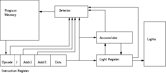
Figure 1. Taken from the lab instructions.
Our circuit is basically a two state machine, the first being fetch and the second being execute. It operated with a memory of 16 lines each of 22bits length. These lines were composed of the first 6 bits being the Opcode (4 instruction bits, 2 jump bits), two 4 bit addresses and the final 8 bits for data. Given an address memory returns contents of that address, but there is no way to write to memory so it only acts as ROM.
Based on the Opcode given our circuit could add bits, rotate bits, shift bits, compare bits and move them between IR, AC and the light register. So, similar to a computer, our circuit can do simple math. Furthermore, the circuit would have a clock and do all operations on the rising edge of the clock signal.
Testing.
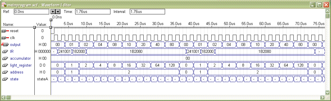
For testing our circuit, we set up our memory such that the commands would shift the light register by one. (in other words, the light register would be multiplied by 2). To test our circuit we first used a waveform editor without the clock divider, and figure 2 shows how the circuit behaved as we expected.
(click on image for larger version)
Figure 2. Simulation of the circuit with the waveform editor. The light register is displayed in decimals for clearer demonstration.
Final Circuit.
Here's a video that shows a simple program we ran on the circuit.
Questions.
Our circuit carries the most basic characteristics of a computer, it can read data from memory, store it in a variety of registers, display output on a bunch of LEDs and control flow of data which allows all of the previous functions. It can also perform a variety of actions on data such as addition, and rotation of bits which could allow it to be used as a calculator.
PROBLEMS ENCOUNTERED
Most of the problems we encountered were during debugging (surprise!). When portmapping the clock divider, we accidentally reversed the order or reset and clk and since everything compiled perfectly we thought the origin of the problem was something else.
Also, one of the components had a conflicting reset activation with the main program (main program was reset when reset = 0 and the component was reset when reset = 1). Again, things compiled and we thought we had a problem with the algorithm.
There weren't many other problems, setting up the altera boards was easy since Adem had already taken E15.
What we learned
This lab was Mustafa's first introduction to VHDL, and although Adem did almost all of the coding it still helped him see the similarities and differences of it from other programming languages. Particularly, learning the way VHDL executed back to back if statements and the way functions in computer languages are different than port maps in VHDL was a good experience. It was also a good introduction to software that is used for coding in VHDL. Furthermore this lab helped clarify the abstract concepts we read in the book and talked about in class, such as memory access and Opcode execution. Mustafa found the instructions a little confusing.
|