ABSTRACT
In this lab we built two state machines. The event timer displayed the time between occurances of a certain event (pressing a button for example). The talking state machines (one receiver and one transmitter) transfered data from the transmitter to the receiver using 'hand-shaking' through a parallel connection.
Task 1 - The Event Timer
The event timer was very similar to the 'reaction timer' we built in lab 3.
However, in this case when the circuit was active the
timer was counting the time since the last event. So instead of a running counter the user observed the time since the last event on the sevent-segment display.
The range of times we needed to handle was between 25ms to 500ms. So we filtered out the events that happened in the first 25ms after an event and we displayed FF on the seven-segment-display when 500ms were exceeded.

Figure 1. ASM chart for the event timer. 'event' is active low.
The event timer starts in the WARMUP state, where it counts up to a value (TA) and we assume that events in during the TA period are due to hardware and user and are unrealistic. For example if we have a user pressing the event button, he will probably press the button for a few milliseconds during which we would not want to record an event (but we still want to start the timer). After TAwe go to the COUNT state, where an event is expected to occur. If the timer, started in the warmup state, reaches a certain value TB then we go onto the SHOW FF state, where the circuit displays FF. In an event occurs in the COUNT state, then we go to the STOP state where the event time is displayed.
If the circuit is in DIPLAY FF state and receives an event (the event button is active low), then it goes to the STOP state again, but keeps displaying FF.
The STOP state resets the timer and goes to the WARMUP state and the procedure repeats.
For this task, we used a component we developed in previous labs which displays time on the seven-segment-display. Since the component and the actual event timer used the same clock, we used variables suck as 'show', 'setzero' and 'showFF' that told the component to display the latest time, reset and show FF respectively. So, if we were in DISPLAY FF state, 'showFF' would be asserted and the component would show FF. We could have implemented the same thing in the event timer algorithm but for simplicity we chose to use existing component.
Task 2 - Talking State Machines
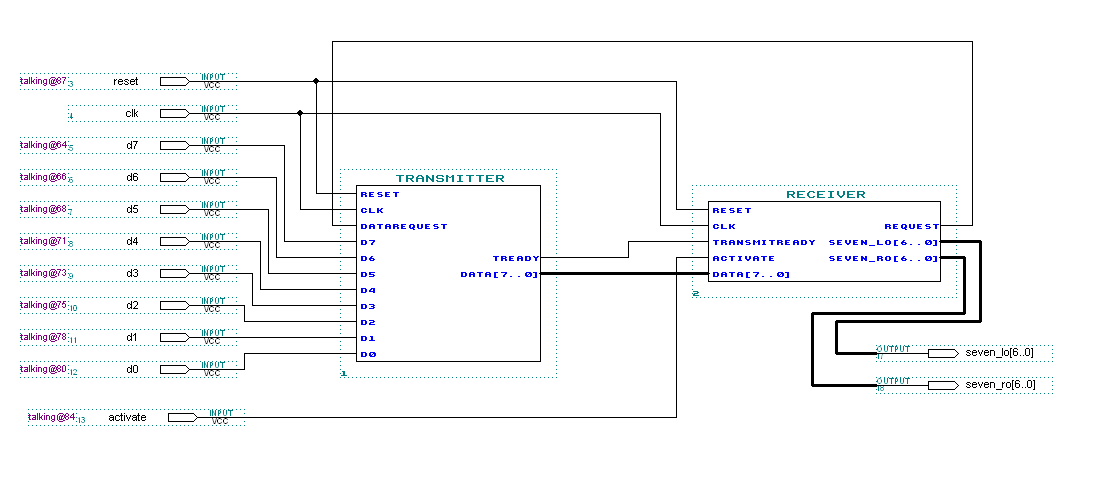
For this task, we built two state machines that communicate with each other via a simple query/response protocol. One state machine is a transmitter [T], and the other one is a receiver [R]. The state machines use a protocol that uses two control lines (TransmitReady and DataRequest) and a set of 8 data lines. The procedure is as follows:
- R tests the TransmitReady line to see if it is not asserted. It repeats this step until the TransmitReady line is not asserted.
- If TransmitReady is not asserted, R requests a transmission of data by asserting the DataRequest line (if user-controlled activate is asserted)
- When T sees the DataRequest line asserted, it places the current data on the data lines and then asserts TransmitReady.
- When R sees the TransmitReady line asserted, it reads the data on the data lines and then de-asserts DataRequest.
- When T sees the DataRequest line de-asserted, it de-asserts the TransmitReady line.
|
The receiver and transmitter components can be seen in Figure 4.
receiver
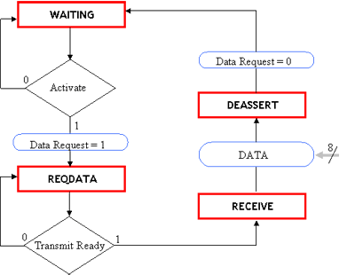
Figure 2. ASM chart for the receiver [R].
Looking from the receiver's point of view, the receiver expects an activate signal (user input) to request data. Once the receiver requests data it waits for the Transmit Ready signal from the transmitter, and upon receiving a transmit ready signal, it gets the data from the data line, deasserts Data Request and goes back to the WAITING state.
transmitter
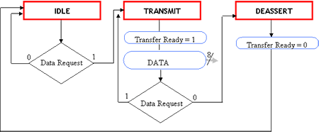
Figure 3. ASM chart for the transmitter [T].
The transmitter is in idle state until it sees the DataRequest signal from the receiver. After this, it asserts Transfer Ready and put the data on the data lines. (We used dip switches as our data - 8 bits). It keeps the Data available until the DataRequest signal is deasserted, and then the transmitter deasserts TransferReady and goes to the idle state.
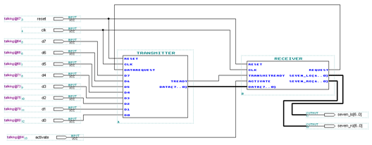
Figure 4. The transmitter and the receiver circuits put together.
The receiver has a component that displays the numbers on the SSD on the Altera Board.
Problems Encountered
Both tasks worked well however we encountered a few problems during the design. For the first task, we wanted to display in decimal mode instead of hexadecimal, which is not a great idea since it's limiting events to withing 100ms rather than 255ms but it is nicer to display the circuit to people working in decimal mode. People don't like using hexadecimal these days, good ol' babylonians... There is also a negligable delay (1 clock cycle) between an event and when the timer starts counting because it takes us a clcok cycle to reset the clock.
In the second part, there was a confusion about whether the receiver should wait for transfer ready in order to be able to request data. We could implement a system where the transmitter sets Transfer Ready by default but we thought it would be better if a user triggered the whole transmission process.
What We Learned
In this lab, we learned about communication between two devices. Sending data between our state machines resembles the data transfer between a printer and a computer or a digital camera and a printer or a computer.
We also learned to use graphical design tools of Altera along with VHDL code. Previously, we had only used either the VHDL code or the graphical tools.
We also learned
|