abstract.
In this lab we were introduced to an extremely common non-linear device, the diode, and some of its more common uses. We learned a little bit about transformers, a component that is in almost every piece of electronic equipment that we own.
power supplies.
part 1:

Figure 1. A half-wave rectifier
Using the circuit shown in Figure 1, we aimed to get an output that was always above 0. Because the diode allows current in one direction and there is some voltage drop over the diode, the output was slightly below (~0.7 V) the input voltage and always non-negative. See Figure 2 for the output and figure 3 for the 0.7 V drop across the diode.
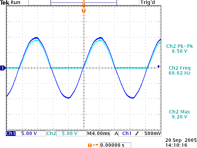
Figure 2. Comparison of the half-wave rectifier input and output.
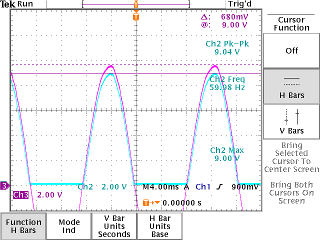
Figure 3. 680mV drop across the diode.
part 2:
For this part, the circuit in part 1 was slightly modified to adjust output such that it doesn't drop down to 0 and it stays around a voltage about 4 V. We put a capacitor in parallel with the resistor to accomplish this. Figure 4 shows the output from the modified circuit. There is still a 0.7 V drop across the diode but the peak to peak voltage drop is about 3.96 V. In the previous circuit, we would expect a voltage drop of about 9 V. Also notice that the addition of a larger capacity capacitor can make the voltage drop less.
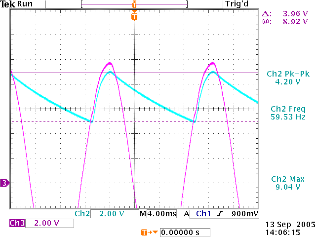
Figure 4. Peak to peak voltage drop using a 47 µF capacitor.
part 3:
We mentioned in part 2 that a larger capacity capacitor would make the ripple smoother. Figure 5 shows the output when we use a 330 µF capacitor. Notice that the voltage drop (0.96 V) is very small compared to 3.96 V with a 47 µF capacitor.

Figure 5. Peak to peak voltage drop using a 330 µF capacitor.
part 4:

Figure 6. power supply using a capacitor and two diodes.
We added a 6.2V zener diode (1N4735) to our circuit and thus added more regulation to the crude power supply from the previous step. Figure 7 shows the output with the new additions.
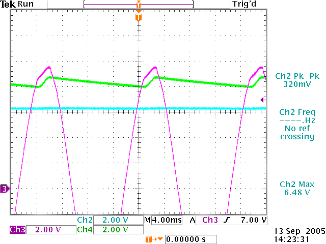
Figure 7. Input voltage and voltage drop across the capacitor and the output voltage.
part 5:
For this part we added another resistor in parallel with R2 from the previous part and compared the performance of the two circuits. Figure 8 shows the output of the modified circuit and it is obvious that the addition of a new resistor hinders the regulation of the signal and causes ripples.
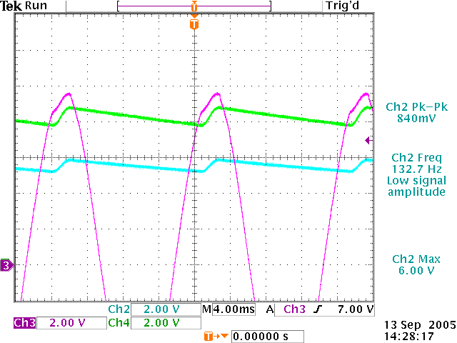
Figure 8. Output of the modified circuit (a 470Ω-5% resistor is placed in parallel with R2 in figure 6)
part 6:

Figure 9. Full wave bridge rectifier
Using the configuration in figure 9, we are always giving some positive input to the system, so we always have a positive input over the entire range of the sine wave and therefore we expect this to work better (but deep inside we know it won't!) Although the full wave bridge rectifier module performed better than the circuit in part 5, it didn't quite do the job the circuit in part 4 did.
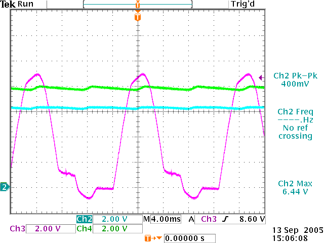
Figure 10. Output from the full wave bridge rectifier module.
part 7:
What we have right now is almost a practical DC power supply, but it's pretty far from ideal; the regulation varies with fairly small changes in load. So as a last step, we add a new component to our circuit: a voltage regulator (we used the 7805) There are two capacitors on the output to decrease variations in the output.

Figure 11. A full wave bridge rectifier with the 7805 voltage regulator.
If we were to replace the transformer with a 10V DC source, the output of the circuit wouldn't change much. In fact, it would be almost identical. Even if we changed the polarity of the DC source the output would be the same because with this configuration we are always allowing about the same voltage in and the capacitors charge up and preserve their charge well enough that the output signal seems quite flat. Figure 12 shows the output of the circuit.
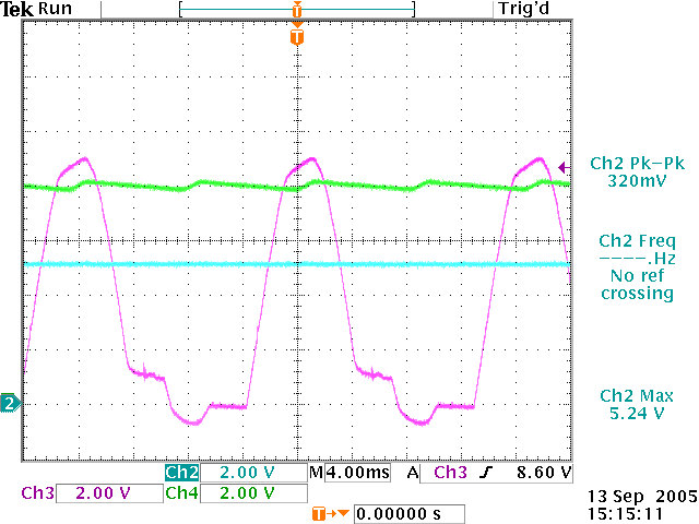
Figure 12. Output of the circuit using a series voltage regulator.
part 8:

Figure 13. Circuit used to get abs(signal) and -abs(signal).
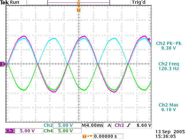
Figure 14. output of circuit in figure 13.
part 9:
If we combine the circuits from part 8 and from part 7, we can build a power supply that will generate both +5V and -5V at 50mA |