Lab 7: 3D Modeling
In this lab, we integrated three-dimensional transformations into our hierarchical modeling system. We also wrote a function that adds a unit cube to a modules. A programmer using our graphics environment can now describe 3D scenes with the same convenience attained for 2D scenes in Lab 5.
Procedure
Our graphics environment continues to follow Prof. Maxwell's Graphics Environment Specification.
We developed seven functions that add new elements to a module. Five of these compute 3D transformation matrices for translation, scaling, rotation about the X-axis, rotation about the Y-axis, and orientation to arbitrary orthonomal axes. The transformations are mathematically analogous to the 2D transformations implemented in Lab 4. We also wrote a function that inserts the six faces of a unit cube centered at the origin, and another that adds the twelve edges of that cube. All insertions operate within the existing hierarchical-modeling framework.
Results
Group Images
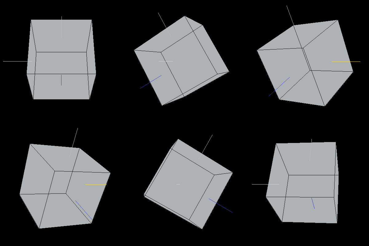
The following animation of random cubes rotating was generated using Prof. Maxwell's test code. Each cluster of cubes should rotate at a constant distance from the Y-axis, but because our graphics system draws overlapping elements in an arbitrary order, the clusters appear to weave. In Lab 8, we develop z-buffering capability that fixes this problem.
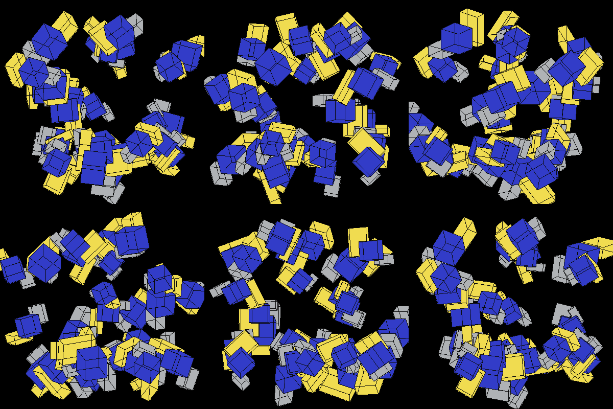
Image 1. Random 3D cubes
The following image is a reference unit cube. The colored lines are also included for reference: the blue line is along the X-axis, the yellow line is along the Y-axis, and the light grey line is along the Z-axis.
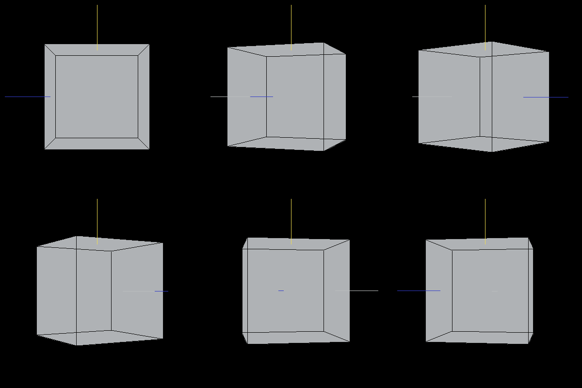
Image 2. A unit cube in default orientation.
The following cube has been translated along each axis. Since the scene is still rotating about the Y-axis, the translated cube appears to make circles in the sky.
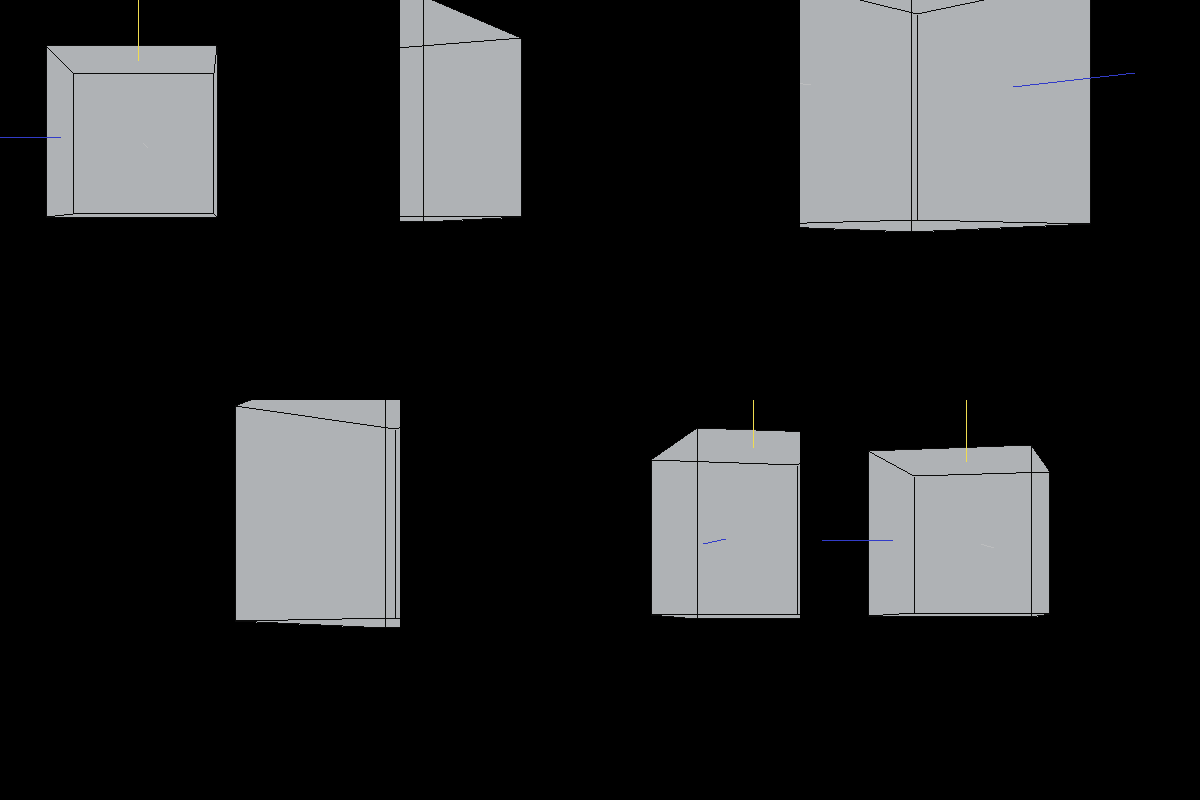
Image 3. A translated cube.
The following cube has been scaled by .5 on the X-axis, .7 on the Y-axis and .1 on the Z-axis.
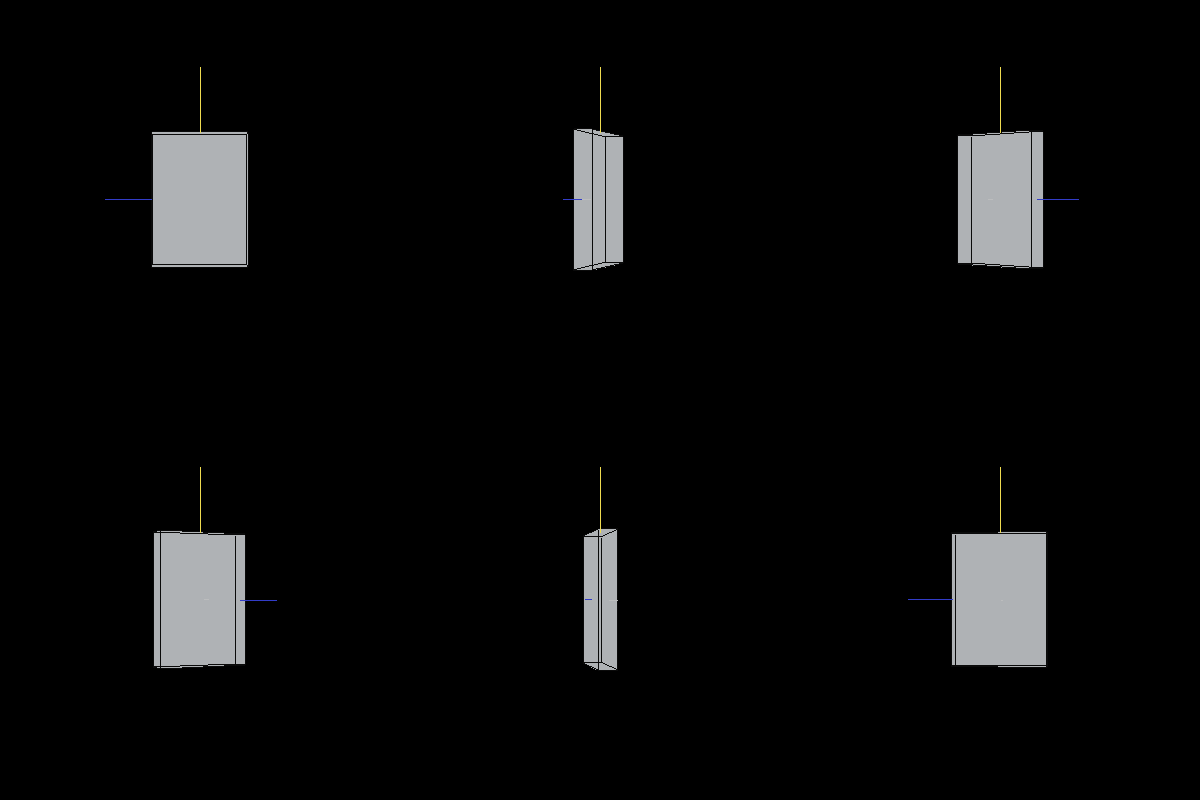
Image 4. A scaled cube.
The following cube has been rotated by 30 dgerees (pi/6) around the X-axis.
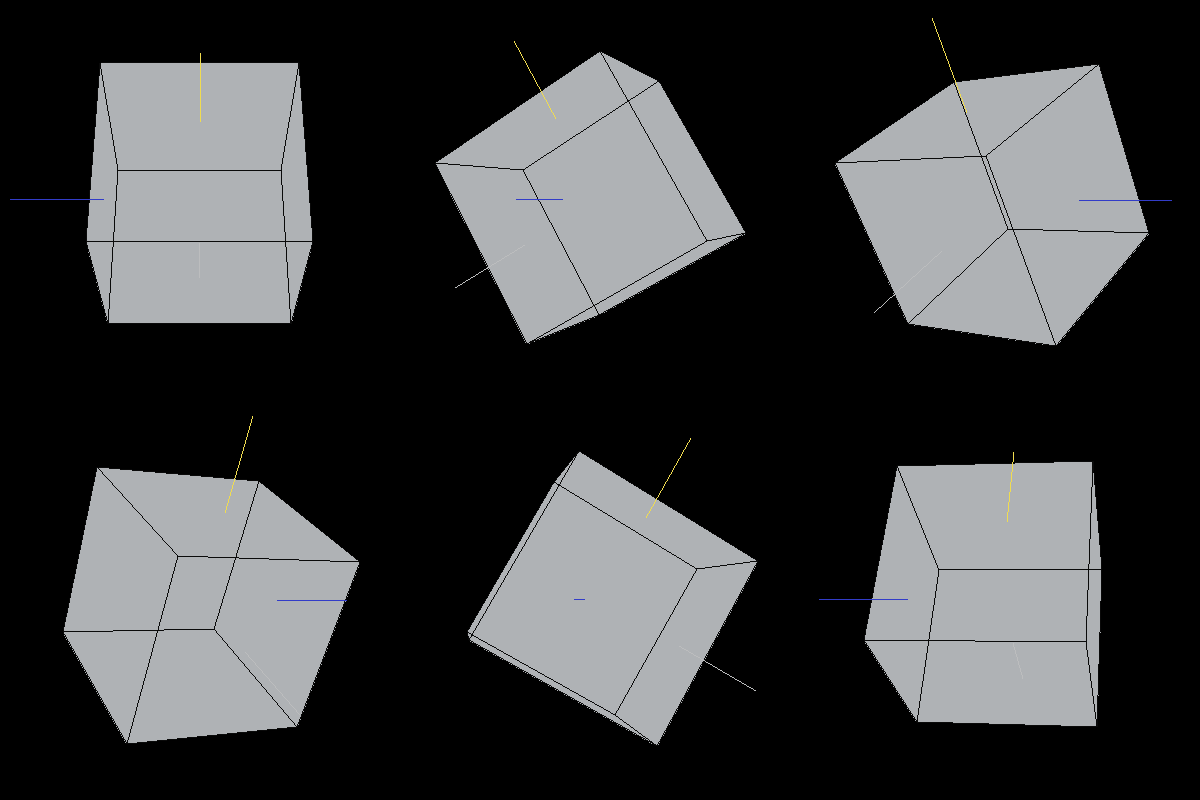
Image 5. A cube rotated about the X-axis
The following cube has been rotated to align the X-axis along the Z-axis, the Y-axis along the X-xis, and the Z-axis along the Y-axis.
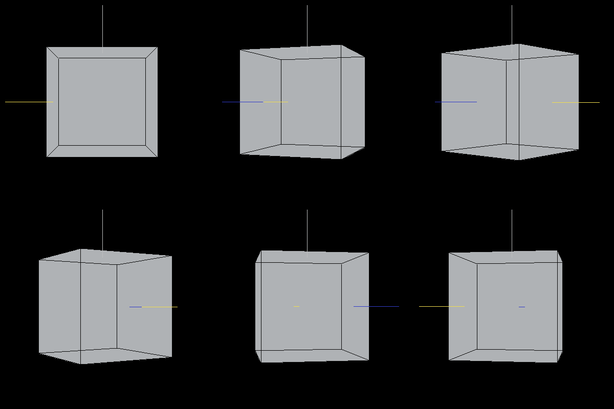
Image 5. A cube rotated to swap axes. Chop chop.
The following cubes have been rotated about the Y-axis by 30 degrees (pi/6). We cannot tell that the rotation has taken place in the first image because the cube is being displayed by rotating it about the Y-axis. The second cube has been rotated from the starting position in Image 5 (with re-aligned axes) so that we can tell the the rotation has taken place.
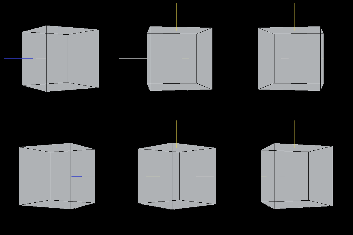
Images 5 and 6. A cube rotated about the Y-axis.
Conclusions and Future Work
Our graphics system now provides elementary support for three-dimensional modeling. In future work, we will add z-buffering for correct and consistent rendering of depth. We will also develop a lighting and shading model.
Appendices
Our code is available with AES256 encryption. The passphrase is only available to Dr. Maxwell.
The library modifications were pair-programmed. Allison generated the demonstration images and wrote the report; David edited it.
