
Lab 6: 3D Viewing Pipeline
In this lab exercise, we added 3-D perspective transformations to our Matrix library.
Procedure
Our graphics environment continues to follow Prof. Maxwell's Graphics Environment Specification.
A perspective projection generates a two-dimensional view of a three-dimensional world as seen by an eye situated within that world. A perspective transformation matrix can be developed from the following parameters.
- The view reference point, or VRP, is a point on the viewplane.
- The viewplane normal vector, or VPN, indicates the positive normal direction of the viewplane. Thus, the VRP and VPN together define the viewplane.
- The viewplane up vector, or VUP, orients the viewplane. If it does not lie in the viewplane, the computed perspective will not be proper.
- The eye itself is located at the center of projection, or COP. In principle, the COP may be at any point behind the viewplane. In our simplified model, however, the COP must be on a line normal to the viewplane that intersects the VRP. Thus, the distance d fully specifies the COP.
- The distances du and dv aree the x- and y- dimensions of the rectangle in the viewplane that constitutes the field of vision. The VRP must be at the center of this rectangle.
- The distance f separates the viewplane from the front clip plane, which lies parallel. No objects between the two planes are drawn.
- The distance b separates the viewplane from the back clip plane, which also lies parallel. No objects beyond the back clip plane are drawn.
The perspective matrix is the composite of the following transformations, most of which we developed in Lab 4. Projection onto the viewplane simply sets the homogeneous coordinate to z/d; the drawer must then divide the x and y coordinates by h to find the actual point where a ray emanating from a given point on an object intersects the viewplane.
- Translate the VRP to the origin.
- Rotate such that the positive-X direction is that of the VPN and the positive-Y direction is that of the VUP.
- Translate the COP to the origin.
- Scale in X and Y such that the field of vision is a unit square in the XY plane, the front clip plane is z = 0, and the rear clip plane is z = 1. This compresses all viewable objects into the unit cube, or canonical view volume.
- Project onto the viewplane.
- Scale to the dimensions of the output image.
Results
Group Images
Image 1 is a unit cube in two-point perspective. Our perspective view parameters match those specified in the lab handout.
- VRP = (.5, .5, -2)
- VPN = (0, 0, 1)
- VUP = (0, 1, 0)
- d = 2
- du = 1
- dv = 1
- f = 0.0
- b = 5.0
The transformation matrices
and transformed vertex points our code generates match those
reported by Prof. Maxwell. In summary, the vertices in mathematical
space are
{(0,0,0), (0, 1, 0), (1, 1, 0), (1, 0, 0), (0, 0, 1), (0, 1, 1),
(1, 1, 1), (1, 0, 1)}.
The placewise-corresponding coordinates in the
100x100 screen space with the given perspective are
{(75, 75), (75, 25),
(25, 25), (25, 75), (70, 70), (70, 30), (30, 30), (30, 70)}.
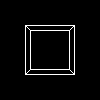
Image 1. A unit cube in Octant I, viewed from a two-point perspective.
The parameters for the following three-point perspective view of the same cube, with a 200x200 screen size, are
- VRP = (-2, 2, -2)
- VPN = (1.6, -.8, 1.2)
- VUP = (-1, 2, 0)
- d = 2
- du = 1
- dv = 1
- f = 0.0
- b = 5.0
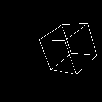
Image 2. The cube of Image 1, viewed from a three-point perspective.
The following images illustrate the effects of varying the VRP, the VUP, du, and dv.
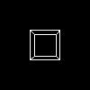
Image 3. As Image 1, but d = 1, causing the cube to occupy less of the view volume.
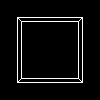
Image 4. As Image 1, but d = 3, causing the cube to occupy more of the view volume.
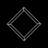
Image 5. As Image 1, but VUP = (1, 1, 0), rotating the cube with respect to the viewframe.

Image 6. As Image 1, but (du,dv) = (10,10), causing the cube to occupy less of the view volume.
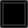
Image 7. As Image 1, but (du, dv) = (.5,.5), causing the cube to occupy more of the
view volume.
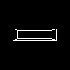
Image 8. As Image 1, but (du, dv) = (.8, .3), stretching the cube in the x-direction.
We draw three-dimensional circles to make a wire globe by evaluating parametric equations for the circle at arbitrarily-defined intervals of the parameter, and connecting the resulting points with straight lines. The larger the parameter interval, the less smooth the approximation. More surprisingly, smaller parameter intervals cause the lines of latitude to become dashed on the far side of the globe; the smaller the interval, the more black space in the line. We do not presently know why this happens.
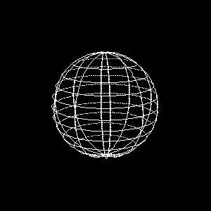
Image 9. A unit wire globe, centered at the origin with poles on the z-axis,
viewed from an aesthetically pleasing perspective.
Conclusions and Future Work
The transition from 2D to 3D drawing was surprisingly straightforward, since the architecture of the existing graphics system components anticipated the need for z and homogeneous coordinates. We expect no greater complications to arise when we integrate perspective into our modeling system.
Appendices
Our code is available with AES256 encryption. The passphrase is only available to Dr. Maxwell.
This entire project was pair-programmed. David wrote this report.