Prepared by Caleb Shetland, Johanna Yoon, Kam Woods,
David Knouf, and Stefan Gary
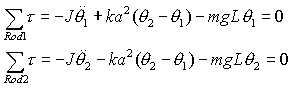
The free body diagrams for the two pendulum system are shown below:
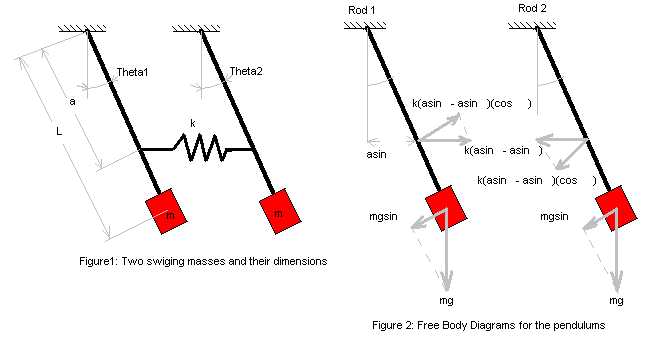
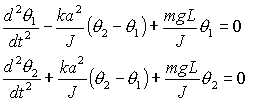
We assume that this model will only be used when the pendulums have a relatively small angular displacement. Thus, the small angle approximations may be made for the sine and cosine terms (sin theta = theta and cos theta = 1). Writing out the summation of the torques on each pendulum yields the following system of equations:
This simplifies to the following differential equation:
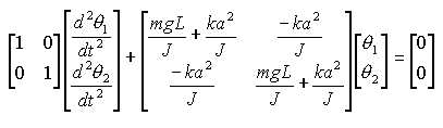
These equations where then loaded into the following matrix system:
We now find the Eigenvalues and Eigenvectors of the system. The various responses (from different initial conditions) represent different weightings of the two natural frequencies of the system. The eigenvalues correspond exactly to the natural frequencies. To find the eigenvalues of the system, we assume that the solution to the differential equations is of the form:
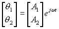
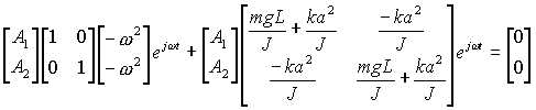
Differentiating this expression and then plugging it and its derivatives into the system:
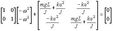
The A matrix and ejwt ĺs cancel out. Adding the matrices together, substituting mL2 for J and then solving for w2 by evaluating the determinant yields:
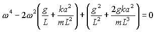
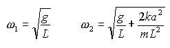
Applying the quadratic formula to solve for w2 results in the following expressions:
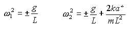
Since a negative frequency does not make physical sense in the system in question, the negative values may be discarded and the values for the natural frequencies of the system are:
The natural frequencies correspond to the eigenvalues of the above system of equations. To find the eigenvectors, we back up to the original system of equations.
The ejwt terms are again canceled out, but we shall now solve for A1 and A2. Therefore, the system of equations becomes:
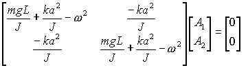
Multiplying out both matrices, plugging in mL2 for J, setting the top equation of the resulting matrix to zero and then solving for the ratio between A1 and A2 results in the following expression:
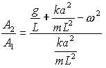
Take w to be the first natural frequency, w1:
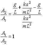
Therefore, the first eigenvector is:

By the same procedure, the eigenvector corresponding to w2 is:

The eigenvectors may be read as the initial conditions that will cause the system to oscillate in the corresponding natural frequency. The vector coupled with w1 represents the situation where the pendulums have identical initial angular displacements. The vector associated with w2 represents equal and opposite initial conditions (its two entries are 1 and -1).