Labs 8 & 9: Illumination and Integration
Ben Mitchell, Zach Pezzementi

A pretty picture of an asteroid; click for a bigger version
A Note to the Reader
So, having just watched Firefox try to use 1.7 Gb of virtual memory on my
machine which has 512 Mb of physical memory trying to load this page, I have
decided that I will henceforth link to all animations and most large
images. Just click on the little "broken image" box, and it should
take you to the actual image or animation. Sorry for the
inconvinience, but I figure it's less inconvinient than having your
machine start to thrash, which is what happens otherwise.
This lab involved doing illumination. We used the Phong reflectance
model, and implemented both flat and Phong shading. Ambient light was
easy, but we had some problems with point sources, as you can see
below.
![]()
Our tumbling cube, with simple ambient light. Not terribly
interesting.
![]()
Here is what happens with point sources
![]()
A first attempt to fix the above problem by incorporating area
The point source is farther away for the second picture than the first.
The problem in both cases is that the falloff of illumination as
surfaces begin to tilt away from the light source is faster than it
seems to us like it should be. This turned out to be due to the fact
that we were doing our caulculations in CVV space, which does not
scale X, Y, and Z symetrically. Doing calculations in world
coordinates fixed this.
![]()
After some more work, things are much better, though there are
still some problems. The light source is close again in this sequence.
![]()
The same sequence as above, but using phong shading. Note that it
doesn't work right; this is because we were calculating the halfway
vector wrong (using the surface normal rather than the illumination
vector)
![]()
Another sequence with flat shading; most of the problems are
fixed, and light anti-aliasing has been done. Specular reflection
has also been turned on.
Eventually, we got everything working. At this point, each polygon can
have parameters that include body reflectance color, surface reflectance
color, and illumination model. The options for the latter are flat and
Phong, since these are the models we implemented. We also borrowed
some of Bruce's code for doing fractal generation of sphere
approximations, and adapted them to work with our system. They
demonstrate the difference between flat and Phong shading quite nicely.
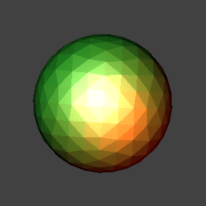
In each of the examples below, a depth-4 recursion was done to generate
the surface. The body color was green, and the surface color was
white. There is a white light source slightly up and to the left, and
a red source down and to the right; both lie on the view plane. Both
are point sources. No ambient illumination was used for these images.
![]()
Sphere approximation, flat shading.
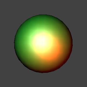
![]()
The same sphere approximation, Phong shading.
It becomes increasingly apparent, especially in the second image, that
the GIF format is fairly limited; the colors are much, much smoother
looking in the original PPM images. A still frame example is given
below.
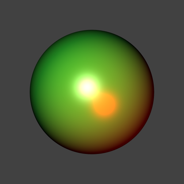
A still frame of the phong-shaded sphere, at higher resolution and
with recursive-depth 7. It's a png, so the colors are true to our
generation. This is what the colors in all the sphere animations
would look like if the GIF format weren't downsampling the color
space.
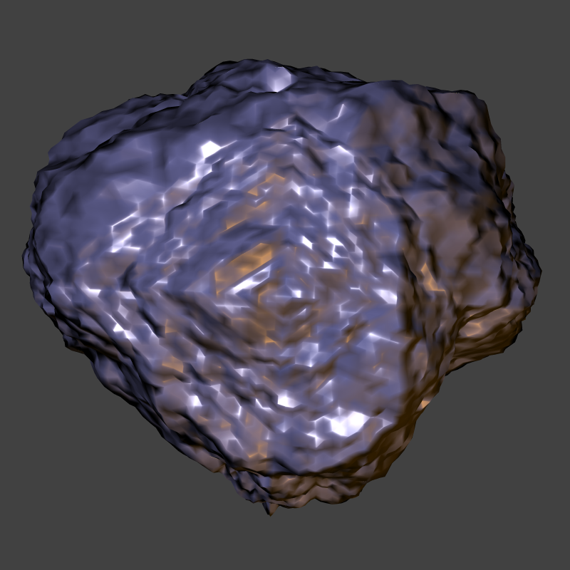
And here is a fun "asteroid" generated again with Bruce's code, with
some modifications to the way it does the permutation of verticies to
get a simulated-annealing affect. The framerate is a bit lower, since
this sequence is high enough poly count that it's fairly expensive to
create (this sequence of 200 frames took 20 or 30 minutes to create).
![]()
A purble-ish asteroid, using phong shading. The two light sources are
similar to those in the above animations. There are still a few odd
visual artifacts that we are trying to track down and eliminate.
While there are still a few noticable problems with our system (mostly
small errors at polygon intersection boundaries), the overall visual
result is fairly good. We are working on debugging these problems, and
have fixed several, but they have proved to be very difficult to track
down, as our rendering system has become rather complex. We hope to
lock down these last few problems before moving on to add new features,
which is why we spent so long on this lab.
Answers to questions:
1. If you use different specular coefficients for the Phong
specularity model, what is the apparent effect of increasing or
decreasing the coefficient? Test this out, don't just make up an
answer. Show the pictures on your lab report so you can visually
answer this question.
The specularity coefficient controls how tight the bright spot of
specularity is. We found we needed a pretty big number to get good
effects; for instance, the specularity in the sphere animations is 50,
and it is 200 for the cube (due to the fact that an entire side of the
cube is just one big flat surface, and the light source is a ways
back). Here are two pictures, one flat and one phong shaded, of the
sphere from the above animations with a specularity of only 10. Note
how the bright spots are bigger.
Flat shading, specular coefficient of 10.
Phong shading, specular coefficient of 10.
2. If you integrated the light sources with your modeling system,
how did you do it?
While we have not yet integrated lights with our modeling system, we
have integrated them with our GraphicWorkspace system, and it is
possible to apply transforms to LightWork objects.
3. If you implemented any other extensions, explain what you did and
how you did it.
Our scanline rendering algorithm now projects the 4 corners of each
pixel onto a polygon, so we can figure out exactly what quadrilateral
in world space a given pixel maps to. We are not yet actually making
use of this information, but it will be useful for doing things like
texture maping and jitter sampling for shadow-ray casting.
Our updated API
Firstly, we decided that it would be benficial to separate the
specificaiton of models both from their animation and from their
rendering. We therefore added a new class, Anim, which is associated
with each model to take care of its animation. It consists simply of
a list of TimeWarps. TimeWarps are transformations which are applied
over a given period of time. Time in an animation is ranged 0 to 1,
and each TimeWarp is specified with a starting and an ending time
within those bounds. TimeRotate, TimeScale, and TimeXlate all inherit
from the base class TimeWarp to allow each of those specific
transforms. To get the transform to take a model from its origin to
where it should be at a time t, you simply call the module's
myanim.get(t), which interpolates each transform in the animation
and returns the result of their concatenation. Here are the relevant
headers:
class Anim{
  public:
    Anim();

    Xform get(double t);

    void addFunction(TimeWarp *tw);
    void clearFunctions();

  protected:
    list mywarps;

    friend class Module;
};

class TimeWarp{
  public:
    TimeWarp() {}

    virtual Xform getXform(double time)=0;

  protected:
    double starttime, timediff, endtime;
    friend class Anim;

};

class TimeRotate : public TimeWarp{
  public:
    TimeRotate();
    /* o defines the point about which to rotate, if not the origin.
     * u and v form an orthogonal(?) basis that defines the orientation
     * of the module at the start and at the end of the rotation.
     * st and et denote start time and end time respectively.
     */
    TimeRotate(Vect o, Vect u_start, Vect v_start, Vect u_end, Vect v_end, double st, double et);
    TimeRotate(Vect u_start, Vect v_start, Vect u_end, Vect v_end, double st, double et);

    void set(Vect o, Vect u_start, Vect v_start, Vect u_end, Vect v_end, double st, double et);
    void set(Vect u_start, Vect v_start, Vect u_end, Vect v_end, double st, double et);

    Xform getXform(double time);

  private:
    Vect origin, u1, v1, w1, u2, v2, w2;

};
We also wished to separate the list of all objects in a scene
from their locations at any specific time during an animation,
but we of course need to know those positions when rendering each
frame of an animation. We therefore added a class GraphicWorkspace
as a place where we do all of our transformations in model space
to get a snapshot of the scene. All of the transformations
used to animate modules are applied before adding the modules to
the GraphicWorkspace, so it only deals with a static scene.
Although the workspace has several public functions, drawModule()
is the only one the user ever needs to call, and it takes care of
everything else nicely. The use of friend classes here is
admittedly ugly, but I remain resistant to just making everything
public.
Here is its header:
class GraphicWorkspace {
  public:
    GraphicWorkspace();

    VectWork* add(const Vect &v) { Vect o(0, 0, 0); return add(v, o); }
    VectWork* add(const Vect &v, const Vect &n);
    EdgeWork* add(VectWork* v1, VectWork* v2); // add an edge
    PolygonWork* add(const PolygonMod &poly);
    void add(const LightWork &l);

    void xformVects(const Xform &x);

    void drawModule(Module &m, double time);
    inline void drawModule(Module &m) { drawModule(m, 0); }

  protected:
    Hash vectList;
    Hash edgeList;
    Hash polyList;
    Hash surfaceList;
    list lights;
    Viewpoint vp;
    GraphicContent bg; // background

    friend class PolygonWork;
    friend class GraphicImage;
    friend class Module;
};
You will notice that GraphicWorkspace has a Viewpoint associated
with it. This is necessary for any kind of projection, in our
case for perspective. Eventually, we intend to allow animations
to be applied to Viewpoints, but for now we just specify the
Viewpoint as follows:
class Viewpoint {
  public:
    Viewpoint() { init = false; }

    Vect vrp; // View Reference Point - World Coords.
    Vect vpn; // View Plane Normal - WC
    Vect vup; // View Up - WC
    Vect cop; // Centor Of Projection - View Reference Coordinates
    Vect copworld; // COP in world coords
    double umax, umin; //x-axis extents, VRC
    double vmax, vmin; //y-axis extents, VRC
    double F, B; //front, back; pos. distance along VPN, F<B
    double xsize, ysize; //size of the image

    Xform cvvvtm;
    Xform cvv2screenvtm;
    Xform finalvtm;

  private:
    bool init;
    friend class GraphicImage;
};
and we initialize it something like this
  vp.vrp.set(0.0, 0.0, -2.0);
  vp.vpn.set(0.0, 0.0, 1.0);
  vp.vup.set(0, 1, 0);
  vp.cop.set(0.0, 0.0, -4.0);
  vp.umax = vp.vmax = 1;
  vp.umin = vp.vmin = -1;
  vp.F = 2;
  vp.B = 8;
  vp.xsize = vp.ysize = size;
So, for example to render a tumbling box, given a box module
already defined, perhaps as a primitive, the code would
look something like this:
First, you would have to set up an Anim and the associated
TimeWarps, in this case two Rotates about different axes.
  Anim position;
  TimeRotate rx[12];
  TimeRotate ry[8];
  Vect v1, v2;
  Vect u1, u2;
  double inc;


  u1.set(1, 0, 0);
  v1.set(0, 1, 0);
  u2.set(0, 1, 0);
  v2.set(-1, 0, 0);

  inc = 0;
  for(int i=0; i<12; i++){
    rx[i].set(u1, v1, u2, v2, inc, inc + (1.0/12.0));

    inc += (1.0/12.0);
  }
  u1.set(1, 0, 0);
  v1.set(0, 1, 0);
  u2.set(1, 0, 0);
  v2.set(0, 0, 1);

  inc = 0;
  for(int i=0; i<8; i++){
    ry[i].set(u1, v1, u2, v2, inc, inc + (1.0/8.0));

    inc += (1.0/8.0);
  }
We set up our rotations as a series of 90 degree rotations here,
because larger rotations were giving problems earlier. The end
effect is 12 90-degree rotations about the x-axis and 8 about the
y-axis for 3 and 2 revolutions respectively about each axis
between time 0 and time 1.
Next, we associate these TimeWarps with a single Anim and set
that Anim as the Module's animation. Finally we render each frame
of the scene.
  for(int i=0; i<12; i++){
    position.addFunction(&(rx[i]));
  }
  for(int i=0; i<8; i++){
    position.addFunction(&(ry[i]));
  }
  box.setAnim(position);


  for(int i=0; i<frames; i++){
    char buf[9];
    string name;
    double t;
    GraphicWorkspace* scene;

    scene = new GraphicWorkspace;
    t = (double)i / (double)frames;

    im.init(size, size, samples, Grey);
    im.setViewpoint(vp);
    scene->add(light1);
    scene->drawModule(box, t);
    im.scanlineRender(*scene);

    sprintf(buf, "%03d.ppm", i);
    name = "cube";
    name += buf;
    cout<<"Writing frame "<<i<<"...\n";
    im.write(name);
    delete scene;
  }
As you can see, t is sampled here between 0 and 1 depending on the
value of frames that was chosen. The Module (box) is then transformed
to its position/orientation/size/etc at that time and "drawn" to the
GraphicWorkspace scene. Finally, this scene is rendered to an image
with our magical scanlineRender() to form each of the frames to be
combined into an animation. The user of course never has to deal with
any of the gooey internals of scanlineRender. She or he just has to
know that it makes the image go. The code is starting to look a bit
less "objecty", but this is mainly due to the increasing complexity
of the problems being addressed.