Lab 7: 3-D Scanline Rendering
Ben Mitchell, Zach Pezzementi

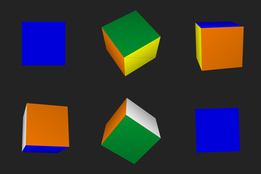
A spinning cube under perspective projection.
Note the Rubik's Cube-like colors which get dimmer with distance.

Rather than implement a Z-buffer algorithm, we decided to implement a full scanline rendering algorithm. We begin by doing the entire graph traversal, storing the entire scene in a single object. Shared edges and points have only a single instance, with multiple objects pointing to them so that adjacency survives transformation into image space.
Once the graph traversal has been done, we transform everything into image space using a perspective projection. It is worth pointing out that the actual "perspective" part of the transformation does not alter the X, Y, or Z values of vectors in world-space; rather, it modifies the H parameter of a vector. Keeping track of the H parameter as a part of the vector allows us to easily get projected values for X and Y (by deviding by H) while maintaining proportional relationships between points in 3-space.
This is important, because it allows us to interpolate in screen space and image space simultaneously. Since we have the entire scene in memory, we simply build a list of edge pairs for the entire scene, and then do a one-pass scanfill rendering step to create an image. For the moment, we have constrained our system to deal only with three-sided polygons, or triangles. Any polygon can be broken up into triangles, so this does not actually hurt the generality of our system. Each triangle has three possible pairings of adjacent edges, but we only actually care about two, because the point of the edge pairs is that, given a pair of edges, for a given scanline we only need to color in the pixels that project from the area between those two edges. One of the three edge pairs will always be made up of two edges which do not actually overlap in Y, and so we do not need to store that pair. We also do not store an edge pair if both edges are trivially invisible, or if one of the edges is a horizontal line.
Once we have this edge-pair list, we scan across the image one line at a time. For each edge pair, we interpolate the world space coordinates for each edge linearly in X, Y, and Z, and for each scanline, we use the points at which the edges intersect the scanline as endpoints to do linear interpolation in Z. At each pixel, we test all the edge-pairs which that pixel projects from between, and take the one with the smallest Z value in world space (the ability to handle lists of pairs so that we can do transparency will be easy to add, and we plan to do so in the future).
Once we know which edge-pair is on top, we pass that edge-pair to our new plot function. This plot function will eventually do all kinds of fancy things like ray-casting and texture mapping in 3D, but at the moment it just scales the color of the thing being drawn based on how close it is to the image plane; closer objects are brighter. This is simply to test and demonstrate the functionality of our 3-D interpolation.

How can you/did you connect your Z-buffer algorithm with the rest of your 3D modeling system?
We connected this with our modeling system quite simply by building the scanline rendering function as a member function of our GraphicImage class. Any number of modules are first drawn to a GraphicWorkspace, and then the GraphicWorkspace is rendered to a GraphicImage. This means that it works with perspective projections and hierarchical models as currently implemented, though at the moment the scanline rendering function only deals with polygons. We came to the conclusion that lines weren't really a useful part of our hierarchical modeling system because they do not scale well; the width of a line is defined by the size of the image, and does not scale proportionally with its length. Therefore, until we implement splines and/or surfaces, polygons are the only valid primitive. Line-like polygons can be created quite easily if needed; such structures were used to create the animations for Lab 5 (this was when the lack of flexibility in lines became clear; when the ship was scaled down far enough that a lot of them could fit in an image, the two lines that were part of the model covered up most of the ship; this was especially apparent with anti-aliasing turned on).
We know z varies inversely with x and y for perspective projection. How does z vary relative to x and y for parallel projection?
Z interpolates linearly under orthogonal projection; nothing is changed by the projection.
What extensions did you do for this assignment, how did you do them, and how well did they work?
The main extension we did was to integrate this with our current system, which allows us to easily create things like the spinning cube, since we can use our hierarchical models, animations, and persepctive projection without doing any extra work. Also, rather than doing the basic Z-buffer algorithm, we implemented an algorithm that separates graph traversal from rendering, and interpolates in X, Y, and Z. This means that for every pixel in the image we know exactly where it came from in world-space, and since we have all the objects in world space defined, we will be able to use this to do things like lighting, shadow-raycasting, and texture mapping much more easily than would otherwise be possible.